Simulation and Emulation for system design
Companies require high quality in their new automated solutions at a low cost and fast delivery. Therefore, test and validation processes become critical for OEMs and system integrators. The testing of the automated systems usually takes place during the on-site commissioning once personnel install the equipment in the actual plant. Incidents at this stage could lead to missing the initial planning. In more severe cases, they may damage the equipment and generate unnecessary additional costs.
Virtual Commissioning
The concept of Virtual Commissioning (VC) is based on realizing the verification and validation of systems against a virtual model instead of in a real automated system.
Different tools and technologies are available in the market for VC.
They use different techniques, such as simulation and emulation, including functionalities focused on different automated systems. Industrial automated system models created using simulation techniques try to provide a similar behavior to the system.
Emulation and Simulation
Industrial automated system models created using simulation techniques try to provide a similar system behavior. This is usually achieved by using simplified approximations or assumptions to understand how the system reacts and analyze its outputs. On the other hand, emulation techniques try to imitate the behavior of a system to perform the same work and produce the same results. The main difference between them is that the emulation model needs the existing control software to work, a Programmable Logic Controller (PLC) or robot program. In contrast, the simulation model does not. This difference makes emulation a more suitable platform for VC, which nowadays is its typical use, but can be more beneficialwhen users apply it throughout the entire life cycle of the system.
Simulation and Digital Twin
Digital Twin (DT) has increased in popularity recently. From the simulation point of view, it’s a concept for describing a new wave in modeling and simulation. While the use of simulation tools was previously restricted to design stages, today, different types of simulation tools are used in testing, validation, or optimization.
In the automated industry, we could define a DT as a multiphysic and multiscale simulation model that mirrors the corresponding physical twin, allowing the extension of the simulation to all life cycle phases of the system.
Simulation in Control Testing
Simulation is used to reduce the time and costs associated with control system development and testing by taking much of the task off the project’s critical path.
Without virtual commissioning, control systems can only be tested properly once the actual equipment they control is in place, complete with products.
Using a model to replace the real equipment, the controls can be developed and tested in parallel with other parts of the project and carried out in an office environment rather than in a factory or a warehouse.
The result is a more thoroughly tested control system, delivered on time and at a lower cost.
Our virtual commissioning models are connected to external control systems, usually on programmable logic controllers or PLCs.
Models may also be connected to any control or data acquisition system using many methods, including HTTPS, TCP/IP, UDP, and sockets.
Modeling Framework and Control Languages
Our technology is unique among industrial modeling systems in offering a choice of control methods to suit the different requirements of its broad range of users.
Control methods fall into two categories – those which are integrated within the products and which are therefore operational at the model clock speeds, and those which are external to the products and run in real time. They communicate with the models using OPC, sockets, Modbus, or other product-specific communications :
- Flexscript, C++/Visual Studio, Phyton, C#/Visual Studio (internal).
- Process Flow, Process Modeler (internal).
- Programmable Logic Controllers (external).
- Co-simulated Virtual PLC (external).
Emulation extended usage
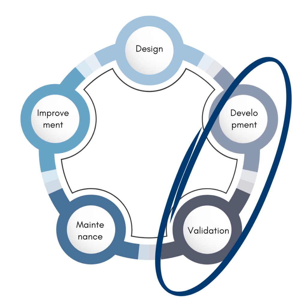
Employing emulation in other phases, rather than development and validation, can help to train expert users and operators, increase the stability and reliability of the system, or aid in implementing system upgrades or modifications without compromising actual production. It can even be used in the design phase to support design decisions and help the sales process and initial discussions with customers. It can also be employed for optimization of industrial systems to achieve efficient operation and performance. The effort to build an emulation model varies depending on the complexity of the system, but this cost will easier be paid off by using emulation in several phases of the life cycle.
This way, emulation would be worth even for those less complex or critical systems.
High Level Emulation
High Level Emulation (HLE) is “Implemented where models already have low-level controls detailed internally, allowing for higher level emulation of larger systems.”
This is usually for testing material flow controls and corresponding warehouse control systems (WCS/WMS).
High Level Emulation is used on warehouse and overall systems automation software testing; it does not involve any lower-level controls as smaller parts of a comprehensive system.
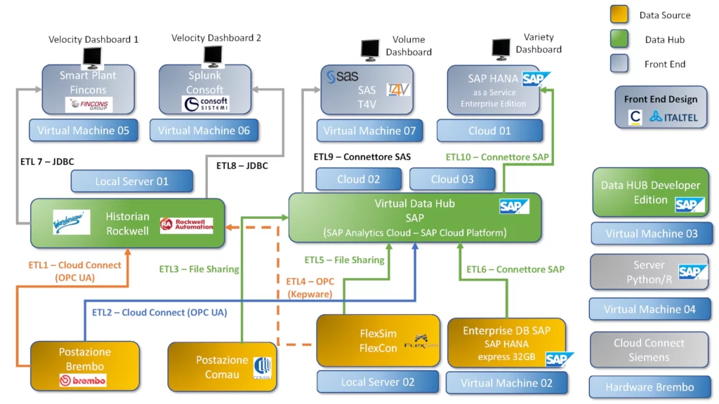
High Level Emulation consists of models connected with PLC (simulated or wired), Process Data Hub, Process Data Collection Systems, and possibly coupled with other simulation tools (co-simulation).
Low Level Emulation
Low Level Emulation (LLE) “Implemented to test lower-level controls such as PLC logic on smaller parts of an overall system”.
This requires the ability to model in detail all 3D aspects, including complex kinematics and (also) physics constraints; in this way, single equipment or part of them can be easily represented with an accurate 3D dynamics representation that can be connected to a PLC program.
Low Level Emulation main drawback is the limited usage with overall systems models because massive 3D graphics limit the simulation/emulation performance.
Low Level Emulation consists of models connected with PLC (simulated or wired), Virtual Controls, Drives, and Automation Frameworks.
Flexcon Emulation: A Virtual Commissioning Module for FlexSim
Flexcon Emulation is an advanced module within the FlexSim simulation software designed to facilitate virtual commissioning for manufacturing systems. By utilizing Flexcon Emulation, users can simulate the behavior of physical components and control logic in a virtual environment, reducing the need for costly prototypes and minimizing errors during real-world deployment.
Flexcon Emulation module integrates seamlessly with FlexSim’s 3D simulation environment, offering a digital twin of the production system. It allows the emulation of control systems, such as PLC, conveyors, and other automated machinery, ensuring that all components work together as expected.
By incorporating real-time feedback from both the simulation and the emulated control system, Flexcon Emulation ensures the system is optimized for performance, reliability, and safety.
It supports collaborative efforts between system designers, engineers, and operators, enabling them to fine-tune parameters and make adjustments before physical assembly begins, ultimately improving efficiency and reducing downtime in the final commissioning phase.
Flexcon Emulation: Key Concepts
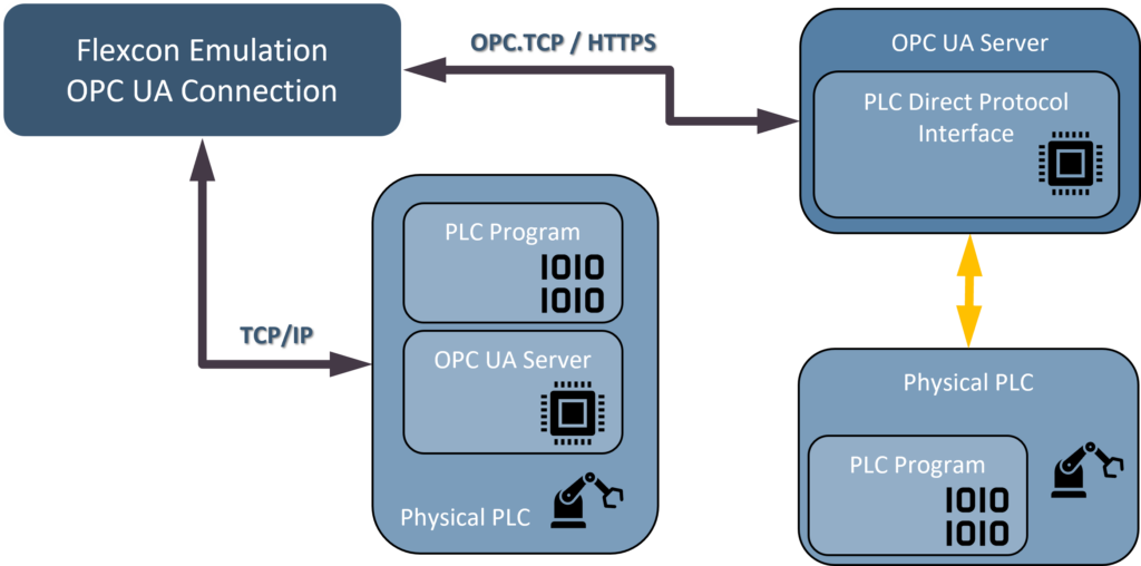
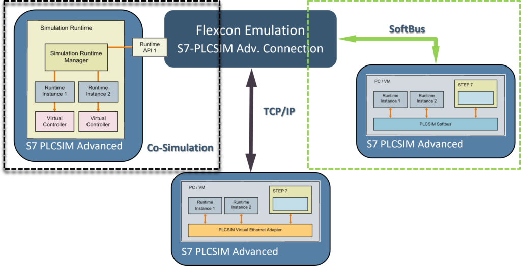
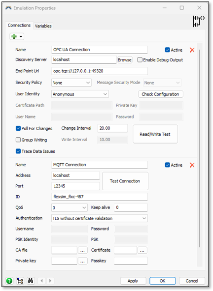
Flexcon Emulation creates a link between FlexSim and external PLCs or clients/servers that communicate with PLCs. It can create multiple connections and define variables for each of those connections.
This tool supports multiple protocols, including Modbus, OPC DA, OPC UA and manufacturer specific like Allen-Bradley, Siemens and Beckhoff.
Modbus and OPC DA connections are freely available from the Flexcon Emulation setup, other connections require an Emulation license, coupled with a FlexSim commercial or educational license.
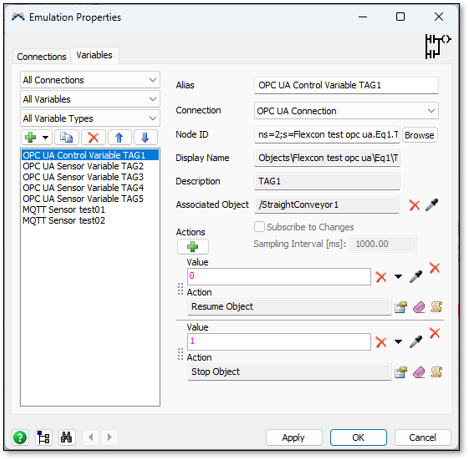
There are different types of Emulation variables that can be added, Sensors (PLC Inputs) and Controls (PLC Outputs).
Sensors are used to write data to the PLC, server or data variable. If the sensor’s connection is active, changing its value will cause that value to be written to the PLC.
Controls are used to read data from the PLC, server or data variable. A control can only be changed if the control’s connection is inactive.
Emulation variables can be managed from the module’ s GUI, in Flexscript and in ProcessFlow.
Flexcon Emulation: Available Connectors
Flexcon Emulation Module provides Basic and Advanced Connectors.
The “Emulation Basic Connectors” set includes OPC/DA and Modbus RTU and is available in all FlexSim product configurations.
The “Emulation Advanced Connectors” set includes OPC/UA, Siemens S7, Siemens PLCSIM Advanced, Beckhoff ADS / Twincat, Allen-Bradley, Mitsubishi MC, Mitsubishi MX and MQTT connections.
For a complete overview of the module capabilities, visit the Flexcon Emulation product page.
Contact Flexcon to discover our emulation-driven solutions.