Optimization of Assembly Lines for the Electromechanical Industry with 3D Simulation
Design and optimization of assembly lines are always a complex challenge. Product variants, space constraints, quality requirements, and flow optimization make every decision critical. In a constantly evolving manufacturing context, companies need solutions that reduce risks and accelerate implementation.
Recently, KONE, a global leader in elevators, escalators, and people flow solutions, faced this challenge at its Northern Italy facility. The goal was to develop a new assembly line for elevator car operating panels (COPs), critical components integrating buttons and displays.
KONE’s engineering team quickly realized that traditional planning tools would not suffice. To address such complexity, they chose an innovative approach: designing and optimizing in a virtual environment with 3D simulation using Visual Components.

The challenges of an assembly line for elevator COPs
In every industrialization project, there comes a moment when complexity becomes evident. For KONE, this happened as the team began translating product specifications into a concrete production flow.
The first issue was quality. The COP faceplates—front panels with buttons and displays—are delicate and susceptible to scratches and dents. Even minor damage could result in rework or scrap, directly impacting costs and lead times. Reducing manual handling became an absolute priority.
Another challenge was managing two product variants of differing complexity. The differences in assembly times and operational flows risked creating bottlenecks and imbalances between workstations.
On top of these challenges were layout constraints: limited space, the need for integration with upstream and downstream processes, and ensuring operator safety. And not least, communication: explaining such a complex process to stakeholders using 2D drawings or spreadsheets proved insufficient.
A simulation-driven approach
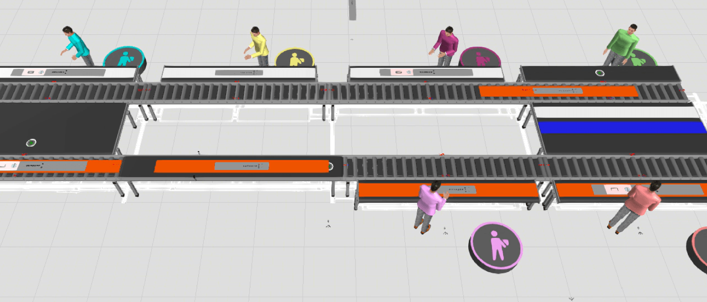
There is great value in being able to virtually test what previously could only be imagined. KONE fully embraced this opportunity by designing a line where each faceplate remains secured on a dedicated pallet throughout the entire process.


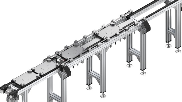
The transport system, based on a Bosch Rexroth TS2 modular conveyor, allows pallets to move between stations without direct handling of sensitive components. This reduces the risk of accidental damage. The production flow includes strategically placed buffers to regulate rhythm variations. Three parallel assembly stations operate in sync to optimize cycle times.
Downstream of the assembly stations, an optical inspection system equipped with artificial intelligence algorithms performs quality checks on the assembled components.
Conforming panels proceed directly to the functional testing stations, while defective ones are automatically redirected to the initial buffer.
This configuration enables the assembly stations to perform the necessary rework operations. It prevents the accumulation of nonconforming products in subsequent phases, maintaining a continuous and efficient production flow.
Buffer in the assembly line: cushion or bottleneck?
In an assembly line, the buffer is a temporary storage area designed to compensate for variations in production flow. A properly sized buffer prevents a delay at one station from stopping the entire process.
However, excessive buffer capacity can cause congestion and slowdowns. Conversely, insufficient capacity exposes the line to frequent stop-and-go cycles.
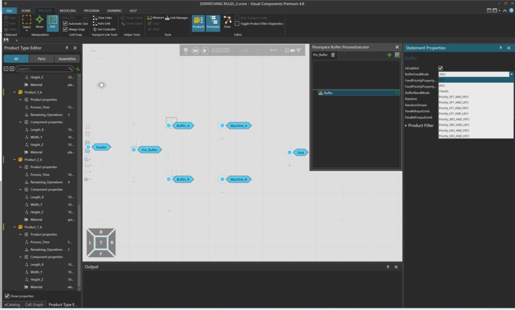
3D simulation allows these dynamics to be modeled, testing different buffer configurations to find the optimal balance between production continuity and efficiency.

A realistic model powered by MTM data
To transform the simulation into a reliable tool, high-quality data is essential. The team integrated MTM (Methods-Time Measurement) standard times for each manual activity: screw tightening, wire connections, functional testing operations.

The simulation included scenarios with:
- three and four assembly stations,
- different numbers of pallets in circulation,
- various buffer sizes,
- a realistic rework rate of 5%,
- and a product mix of 30% simple COPs and 70% complex COPs.
Each scenario was tested over full production shifts. The results provided concrete data to make informed decisions.
The optimal configuration
It was in the details that the simulation made the difference. The analysis showed that three well-balanced stations were sufficient to meet production targets. The ideal number of circulating pallets was found to be ten.
With fewer than ten pallets, some stations risked idleness. With more than ten, the system became congested without productivity gains. This balance—difficult to identify with traditional tools—clearly emerged thanks to iterative simulations.
Results and benefits
The new COP assembly line was successfully launched. 3D simulation delivered:
- a continuous and interruption-free production flow,
- reduced manual handling and defects,
- improved team communication through a visual representation of the process.
This project demonstrated how simulation transforms planning from a theoretical exercise into a data-driven process.
From training to project delivery: Flexcon’s approach to Visual Components
Adopting Visual Components is more than installing software. It requires expertise, vision, and a partner who supports the transition until reaching full autonomy.
Flexcon guides enterprises through a comprehensive path:
🔹 technical training to build an internal, competent team
🔹 support in initial projects to deliver tangible results quickly
🔹 ongoing consultancy to identify the best solutions and optimize processes
The approach adopted in the KONE project reflects how Flexcon operates with enterprises across various industries: electromechanical, automotive, logistics, supply chain, packaging, healthcare, and more.
Contact Flexcon: request a free, personalized demo of Visual Components.
