Modeling Robots in Visual Components: from geometry to realistic simulation
Given the increasing complexity of production systems, modeling industrial robots in virtual environments has become an essential technology. But what does it really mean to “model a robot” in a 3D simulation software like Visual Components? What kind of data and behavioral logic do we need to accurately replicate a robot’s functionality in its real-world context?
In this article, we explore the key steps, required data, and technical challenges that our project engineers face every day to create realistic robot models, ready for production cycle simulation, virtual commissioning, and offline programming (OLP).

The data required to model robots: geometry and kinematics
Every robot model is built on two fundamental data blocks: 3D CAD data and kinematic data.
3D CAD data, such as STEP or IGES files, represent the physical geometry of the robot. These files are often obtained from manufacturers, their commercial partners, or directly from clients.
Kinematic data refers to the specifications describing the robot’s mechanical motion: joints, limits, speeds, orientations. This information is typically available in manufacturers’ technical datasheets and describes the robot’s dynamic behavior.
In some cases, acquiring and managing both kinematic and 3D geometric data can pose challenges. While kinematic data is often readily available, handling CAD files may be problematic in software environments that lack robust format support or interoperability.
Visual Components overcomes these limitations with broad CAD format compatibility and enables the smooth integration of existing geometries into simulation environments.
📎 CAD Compatibility in Visual Components
Visual Components supports a wide range of 3D CAD file formats, enabling easy integration of existing components into simulation projects.
See the full list of supported formats → Click here

The details that make the difference
To go from a static model to a fully functional and simulatable robot, more than shape and parameters are needed. A realistic simulation requires precise reconstruction of:
- the estimated joint accelerations, often missing from datasheets, but derivable through technical expertise and related parameters.
- the zero reference position: different from the general “home” position defined by manufacturers, this is the true simulation starting point.
- the robot origin, which varies by manufacturer (e.g., floor-level for KUKA, central body for Fanuc).
- the directions and conventions of coordinate axes, which are not always standardized but are critical for spatial orientation.
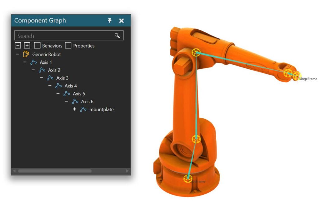
- the joint names and kinematic configuration, sometimes defined using Denavit-Hartenberg parameters, when available.
Aligning coordinate origins: interoperability and programming

One critical step is aligning the manufacturer-defined origin with the Visual Components system origin. Visual Components adopts a unified reference system, with the Z-axis oriented upward from the floor. This ensures consistency across models and facilitates component interchangeability within factory layouts.
Nonetheless, the robot’s original coordinate system is preserved to maintain programming accuracy and compatibility for real robot execution and point teaching.
Behaviors and validation
Once they define geometry and kinematics, our engineers implement the intelligent behaviors that enable realistic robot functionality:
- Kinematics: to define the robot’s movements and joint relationships.
- Robot controller: a proprietary motion planner that mimics the robot’s actual behavior and enables parametric adjustment.
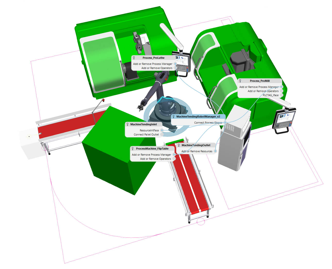
- Interfaces: to ensure interoperability, plug-and-play mounting, end-of-arm tool tracking, and pedestal attachment.
Our team validates each robot model through internal testing and, whenever possible, in close collaboration with the client or the robot manufacturer. We download the program created in Visual Components to the real robot’s controller and execute it to verify its accuracy and consistency.
Why choose Visual Components to simulate industrial robots?
Visual Components offers a growing library of over 3,600 components, including 2,137 ready-to-use robot models. Its tools allow for fast and accurate modeling, with generic motion planners and modular interfaces—ideal for automation projects, collaborative robotics, robotic welding, and offline programming workflows.
Choosing Flexcon as your ideal partner for robot modeling and training
At Flexcon, we don’t just deliver custom robot models for digital twin and virtual commissioning projects — we also empower professionals to become autonomous simulation experts through advanced, certified training.
One of our flagship programs is Visual Components Modeling: a hands-on, expert-level course designed to give you full control over your robot components and behaviors in simulation.
In just three intensive days, you’ll learn how to:
- Set up PLC connectivity using OPC-UA for virtual commissioning scenarios
- Import and manipulate 3D CAD files
- Create components from scratch or based on existing ones
- Define behaviors using properties and behavior atoms
- Simulate dynamic behavior using built-in physics tools
- Extend functionalities with Python scripting
Contact Flexcon: request a free and personalized demo of
Visual Components.